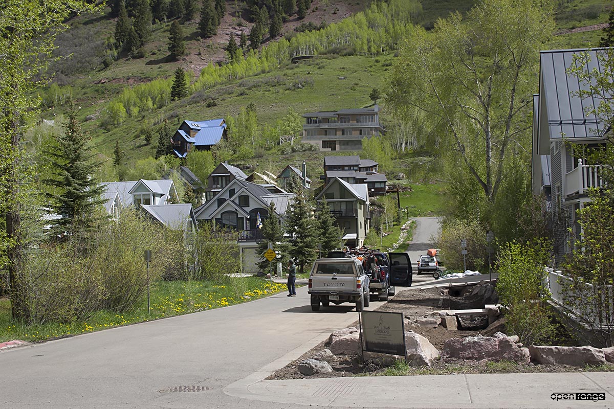
This post describes the process for matching a 3D computer model of a building into a site photograph. Not every exterior rendering requires a photographic match. For some projects, such as this one, it can be required.
Matching a 3D computer model of a building into a site photograph requires that a number of factors are accounted for and verified. The goal is to create a view of the 3D computer model that matches the parameters of the camera used to take the actual background photograph. I’ll use a recent project for a proposed residence in Telluride, CO to demonstrate how this is accomplished.
 The first step is to acquire and import reference material for horizontal positioning. Site plans are usually required for this. This project specified that a view of the proposed residence be shown from a considerable distance away. Below is a screen capture showing a base map of the Town of Telluride with the proposed house footprint located on the corresponding lots.The highlighted icon is a virtual camera that is placed on the map at the location where the photograph was taken. This ensures that the distance and angle from the subject house to the camera are matched.
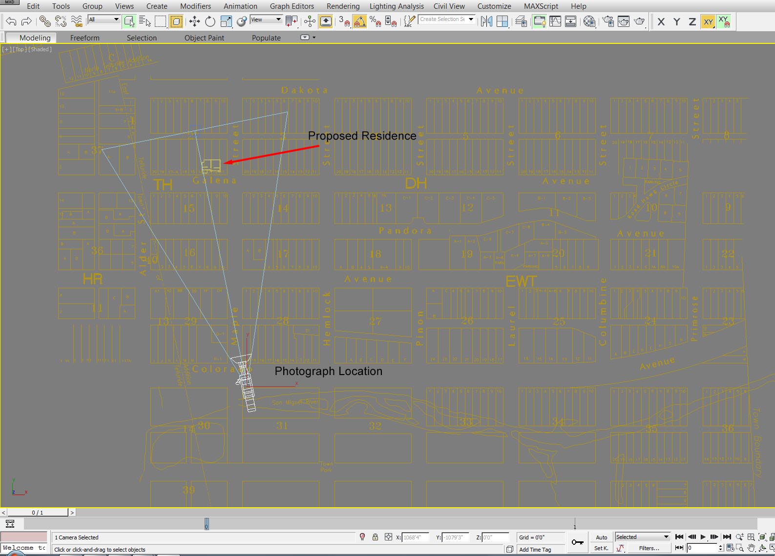 Next vertical positioning is required. The 3D house model is positioned at the elevation specified on the plans. The virtual camera is set to the elevation of the photograph location, plus five feet to bring it up to eye level. Architectural drawings, topographic maps, gps or survey data may be referenced for elevation values.
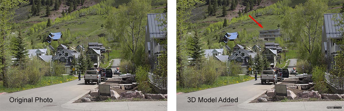
The virtual camera lens focal length or zoom factor must be set to match the focal length/zoom factor of the camera that took the photograph. This rendering is intended to simulate how the house would appear to a person standing at the photograph location. The apparent size of objects as seen by normal human vision is most accurately reproduced by a 50mm focal length lens and that is what was used in this photograph. If the photo was taken with a more zoomed in setting, the house and surroundings would appear larger than if viewed by the naked eye. Conversely if the photo was taken with a wider angle lens the house would appear smaller. For this example the virtual camera focal length must be set to 50mm so that it will match the focal length used to take the photograph.
Reference objects on the site are used to verify the photograph match. These reference objects help in matching the aim point of the camera, both left/right and up/down. In this case a couple of prominent trees on the site were located on the site plan. In addition I set and located three 10′ white posts in positions near to three of the primary corners of the house. These reference posts appear in the site photograph. They are shown in the cropped section of the site photograph below.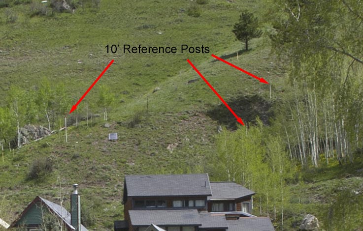 Within the 3D scene I created three virtual 10′ posts and positioned them in the matching locations and elevations. The screen capture below shows how these virtual posts match up with the actual posts in the photograph. The actual posts are painted over with a red color so they can be seen more easily. This is an important and needed step in verifying that the computer model matches the site photograph. If the virtual reference objects do not align with the actual reference objects, something is off.
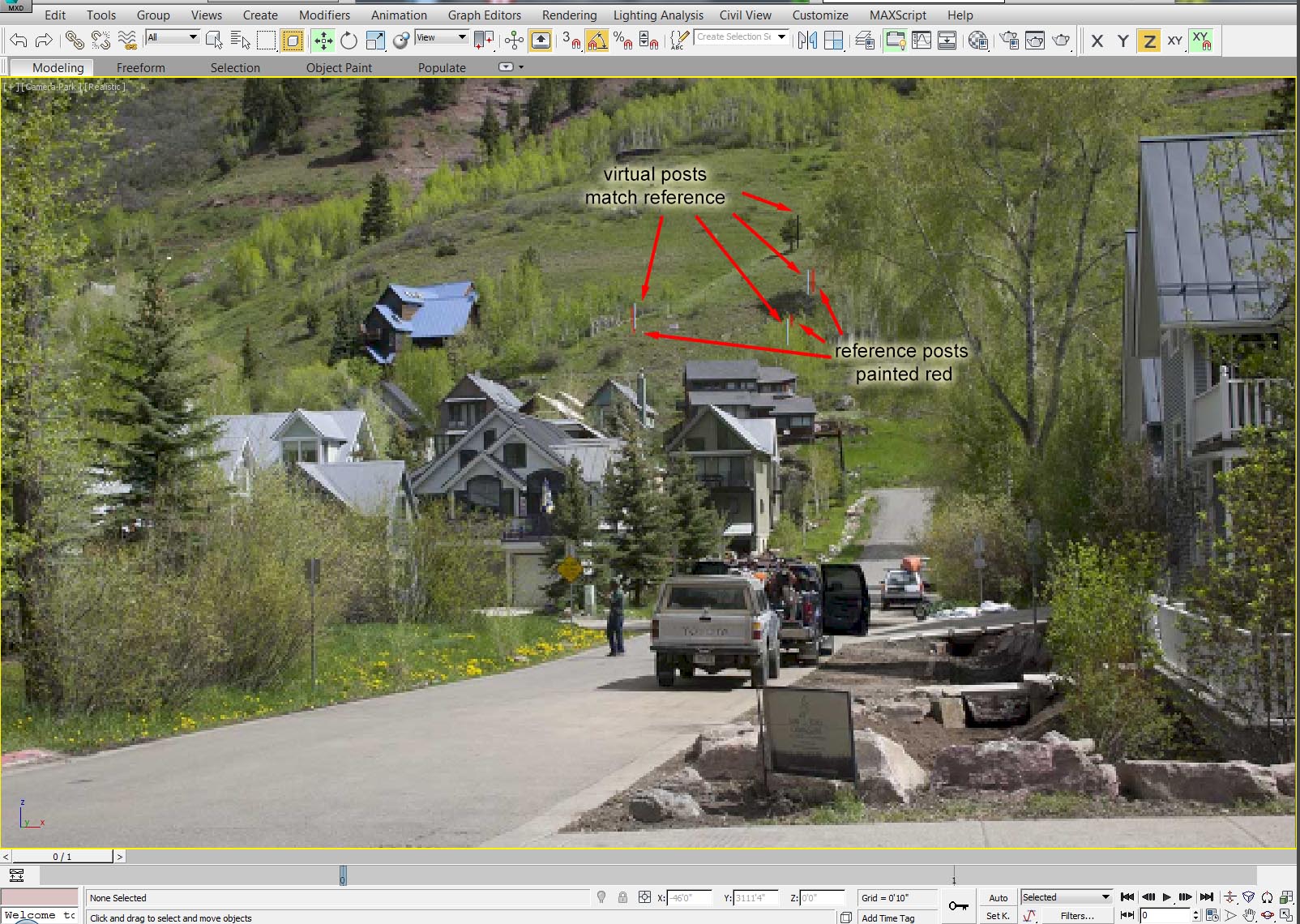 So that is an overview of what is typically involved in creating an accurate photographic match and simulation. Every project is unique and can have a greater or lesser need for accurate matching to site photography. Some renderings may have an entirely simulated foreground and background and not use site photography at all. Others, such as this project, are to be submitted to design review boards and accurately matching into a site photograph is important.